Ok-Vise logo
Here you find information how to use our products
Multi-Rail RM Components for modular workholding system.

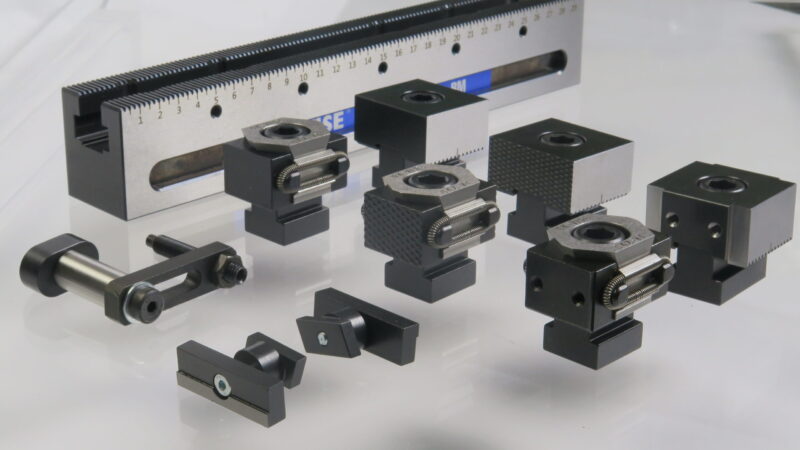
How to use Multi-Rail RM

Assembly on various platforms

Multi-Rail RM base rail can be installed on many different platform types. The most common are grid-, blank- and a t-slot platform.

This video shows you how to install Multi-Rail RM base on grid platform M12 50x50mm

When base rail is installed on grid platform M12 we recommended you to use 2 pcs of shoulder bolts OKSB12-45 in positioning holes and in remaining holes D912 M12 x 45 bolts

By definition, grid platform has all positioning holes and threads ready (Multi-pupose holes).
The set AD-RM-n includes n pieces of bolts, where 2 bolts are type OKSB12-45 and the remaining ones (n-2 pieces) are of type DIN912M12x45.

When a Multi-Rail system is installed on the grid or blank platform, most typical way of installation is to use two shoulder bolts for positioning and DIN912 bolts for remaining holes.

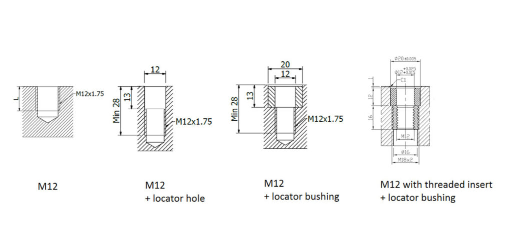
Shoulder bolt requires a precise 12 mm hole. Additionally, bushings and/or threaded inserts can be used.
For the standard bolts simple M12 thread is needed. In aluminium platforms, threaded inserts are recommended.

Inserts and platforms are available through the OK-VISE global distribution network.

M12 threads
threads

When assembled on T-slots assembly we recommended using M-T1 machining option and positionining keys, then base rail positionning is faster and easier. When rail is assembled parallel to T-slots please use standard DIN912 bolts and T-slot nuts. When rail is assembled 90 degrees to T-slot direction then use fastening clamp ICI-12 set with proper size T-slot nuts and DIN912 M12 size bolts.

Installation clamps

T-slot type A set enables installations parallel to T-slots.
T-slot type AB set enables installations parallel and perperdicular to T-slots.
AD-MT-xx contains machining of keys M-T1 with batch startup cost BS-1 (this is once per production order), keys LK-18xx (2 pcs) and screws DIN7984M6X10 (2 pcs).
AD-BT-xx contains installation one bolt DIN912M12X45 with T-slot nut DIN508-M12-xx.

xx = T-slot widht. Most typical ones are 14, 16 and 18 mm.

Multi-Rail RM adapter sets:

Platform
Blank
Grid M12
T-Slot A
T-Slot AB
RM-100
AD-RM-2
AD-RM-2

AD-MT-xx

AD-BT-xx (2 pcs)

 
RM-200
AD-RM-3
AD-RM-3

AD-MT-xx

AD-BT-xx (3 pcs)

AD-MT-xx

AD-BT-xx (4 pcs)

ICI-12 (2 pcs)

RM-300
AD-RM-5
AD-RM-5

AD-MT-xx

AD-BT-xx (5 pcs)

AD-MT-xx

AD-BT-xx (5 pcs)

ICI-12 (2 pcs)

RM-400
AD-RM-6
AD-RM-6
AD-MT-xx
AD-BT-xx (6 pcs)
AD-MT-xx
AD-BT-xx (6 pcs)
ICI-12  (3 pcs)
RM-500
AD-RM-7
AD-RM-7
AD-MT-xx
AD-BT-xx (7 pcs)
AD-MT-xx
AD-BT-xx (8 pcs)
ICI-12 (4 pcs)
RM-600
AD-RM-8
AD-RM-8
AD-MT-xx
AD-BT-xx (8 pcs)
AD-MT-xx
AD-BT-xx (8 pcs)
ICI-12 (4 pcs)
RM-700
AD-RM-9
AD-RM-9
AD-MT-xx
AD-BT-xx (8 pcs)
AD-MT-xx
AD-BT-xx (10 pcs)
ICI-12 (5 pcs)


Stoppers

Stoppers can replaced to documented position positioning be using the scale in the base rail and mark in the stopper. In most stopper types the bolts are tightened with 10 mm allen key to 100 Nm torgue.

Clamps

Clamps expand when tightening the bolt with allen key, tightening torque transforms to clamping force. Please remember that a stopper module is needed on both sided of any clamp module.

Parallels

This instruction shows how to install parallels with T-nut, like models RMP-1, RMP-1H8 and RMP-2.
There T-nut of the parallel goes into base rail-slot, and when parallel bolt is tightened the T-nut rotates clockwise in the rail..

Side guide

Side guide offset is adjusted using treaded rod and nut. When offset is right the nut is used for locking.Side guide type RMP-M1 is with magnet and RMP-1 with M6 screw.

Magnetic side guide its easy and fast to remove after workpiece has positioned.

Do You need help or missing something?

Please register to download the step file.

Login