Frequent loading stops
Machining one workpiece at a time can require frequent operator attention. After a short cycle, the machine may wait while the operator finishes another task.
STAND-ALONE MACHINING CENTERS
Machine more workpieces between loading stops and reach more surfaces without repositioning the part. OK-VISE workholding helps you reduce repeated handling and make better use of your existing machine.
COMMON WORKHOLDING CHALLENGES
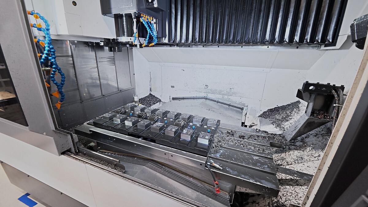
Frequent loading stops, extra repositioning and unused table space can limit how much work you complete with your machine.
Machining one workpiece at a time can require frequent operator attention. After a short cycle, the machine may wait while the operator finishes another task.
Clamps or fixture structures can obstruct machining surfaces, requiring the part to be unclamped, repositioned and located again.
A fixture arranged for one workpiece may leave room for additional parts unused, even when the job is suitable for multiple workpiece clamping.
THE OK-VISE APPROACH
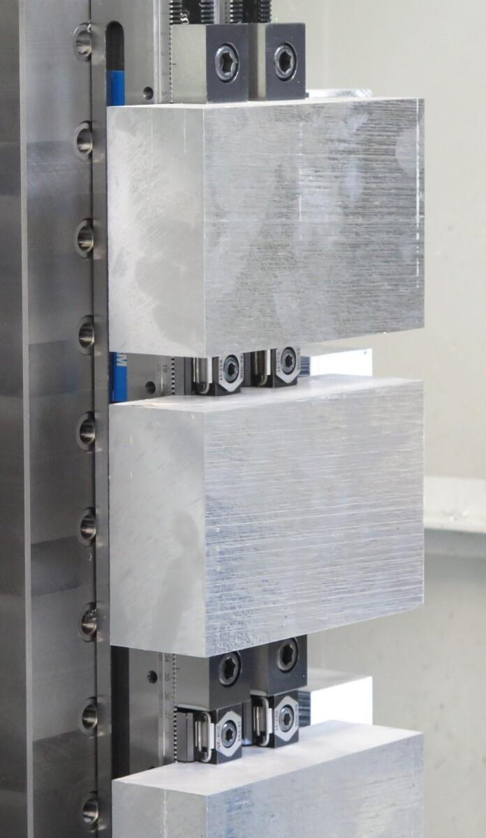
OK-VISE low-profile clamps hold workpieces against locating elements while keeping machining surfaces accessible. Use them in an adjustable Multi-Rail layout or integrate them into a dedicated fixture.
Compact clamps leave room for additional parts. Match the spacing to tool paths, chip clearance and loading access.
Position clamps clear of the areas being machined. A suitable layout can reduce the need to unclamp and reposition the workpiece.
An exchangeable fixture plate and a suitable locating interface allow preparation to overlap with machining. The prepared fixture can then be installed and checked during changeover.
With modular workholding, clamps, stops and supports can be repositioned for different workpieces. Reuse suitable components as the workload changes.
Clamping several workpieces lets the machine run longer before the next loading stop. This can give the operator time for inspection, deburring or preparing the next job.
Position and clamp the workpieces in a layout that provides clear access for loading, cleaning and tightening.
Where the process allows, use each tool on several workpieces before changing tools. This can reduce tool changes per part.
Remove the machined parts, clean the locating surfaces and load the next workpieces. Loading is grouped between machining runs.
Explore clamps and fixture systems for multiple workpiece setups, better tool access and practical changeovers.
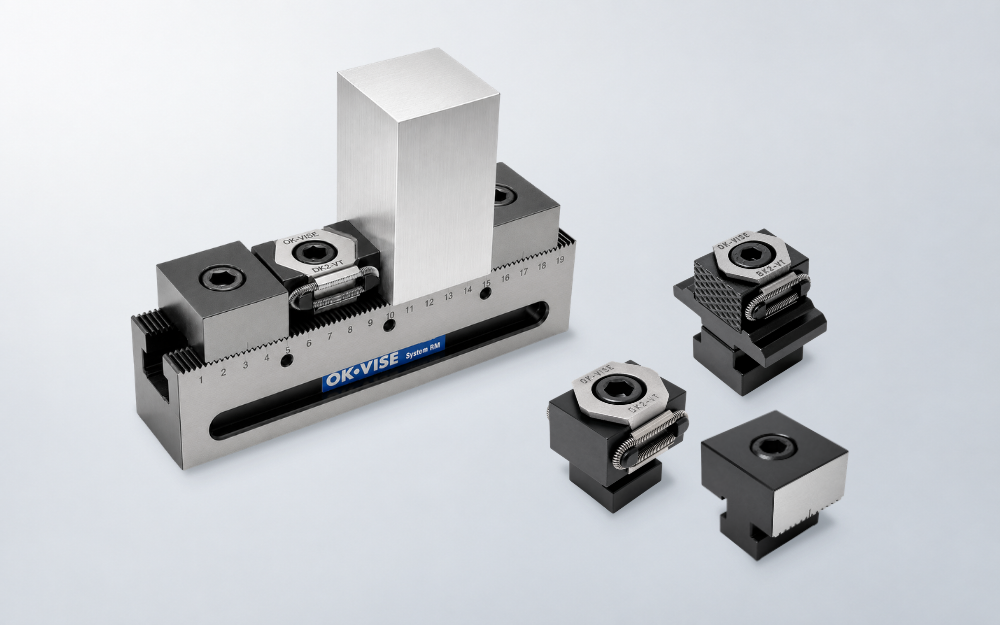
Arrange clamps, stops and supports for one or several workpieces. Adjust the layout when part dimensions or production requirements change.
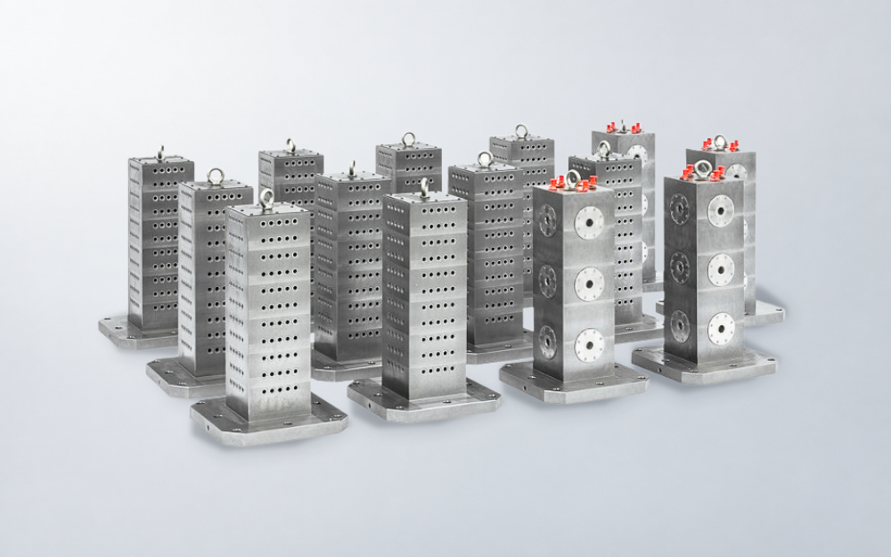
Use tooling blocks to arrange fixtures across multiple faces. Add a suitable zero-point interface where complete fixture plates need to be exchanged frequently.
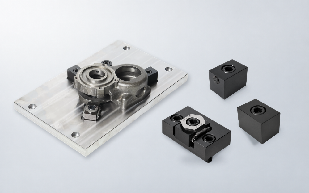
Combine standard clamping and locating components with a custom fixture base for specific workpieces or recurring jobs.
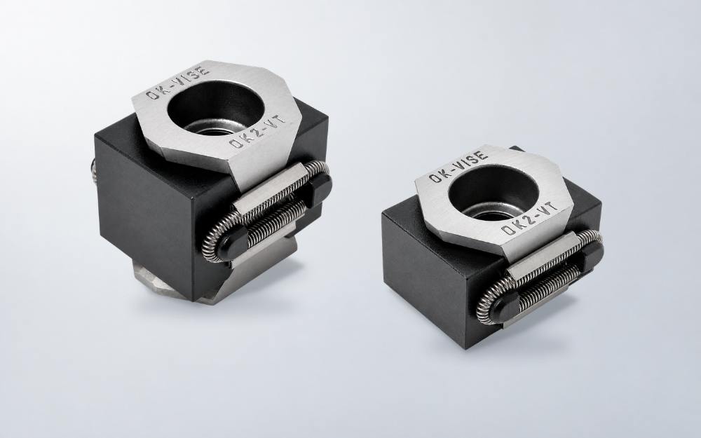
Hold workpieces with compact clamps that leave room for machining. Use them in your own fixtures or as part of an OK-VISE system.
CUSTOMER STORY — IGNETAS UAB
Ignetas UAB machines an aluminium component requiring three setups on a small 3-axis machining center. With traditional machine vises, short cycles required frequent operator attention.
A dedicated pallet with OK-VISE low-profile clamps held six workpieces across the three setup stages. Production time per part fell from 2 min 25 s to 1 min 15 s. The 2.5-minute machining cycle also gave the operator more time for other tasks between loading stops.
Application example
For suitable parts, separate stations in the same fixture can hold blanks for the first operation and partly machined workpieces for the second. Once production is running, the loading sequence repeats as follows.
Unload the completed workpieces from the second-operation stations and clean the locating surfaces.
Transfer partly machined workpieces from the first-operation stations to the second. Load new blanks into the first stations and secure all workpieces.
The program machines the workpieces at each station in sequence. Each station uses locating and clamping suited to its operation.
The main opportunities are fewer loading interruptions and tool changes per part. Better tool access may also reduce repositioning. The cutting time required for each part may remain unchanged, so compare the complete process, including loading, tool travel and handling.
Installation can be adapted to grid plates, T-slots, fixture plates and other suitable machine interfaces depending on the application.
Choose a practical number based on tool access, chip clearance, loading effort and the required batch size. Filling every available space is useful only when the full machining and handling process works well.
DISCUSS YOUR APPLICATION
Tell us about your workpiece, machine table and current machining sequence. Include typical batch sizes and the number of setups needed to complete the part.
We can help assess opportunities for multiple workpiece clamping, better tool access and simpler changeovers.

Prefer local support?
"*" indicates required fields