Workholding Solutions for
All Platforms – All Workpieces
Workholding Solutions for All Platforms - All Workpieces
Product categories
CLAMPING TECHNOLOGY FOR LEADING BRANDS
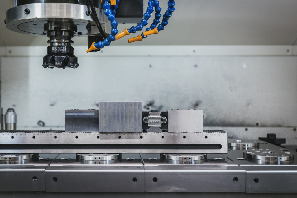
Revolutionize Your workholding with OK-VISE®
The trusted global leader in workholding fixture solutions for CNC machining centers and milling machines. As the original inventor of the wedge-operated Low-profile Clamp, OK-VISE® has been at the forefront of fixturing innovations for years.
Our high-quality components and fixturing systems ensures a secure hold on the widest range of workpiece types, sizes, and materials on any workholding platform. Discover the difference OK-VISE® can make in your machining process today.
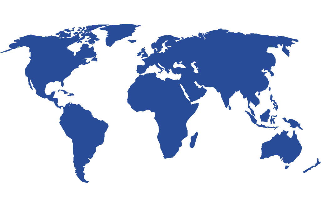
Where can I buy the products?
We sell our products through our global distributor network. Today we have distributors in almost 40 countries world wide. Find your local distributor and ask for a quote!
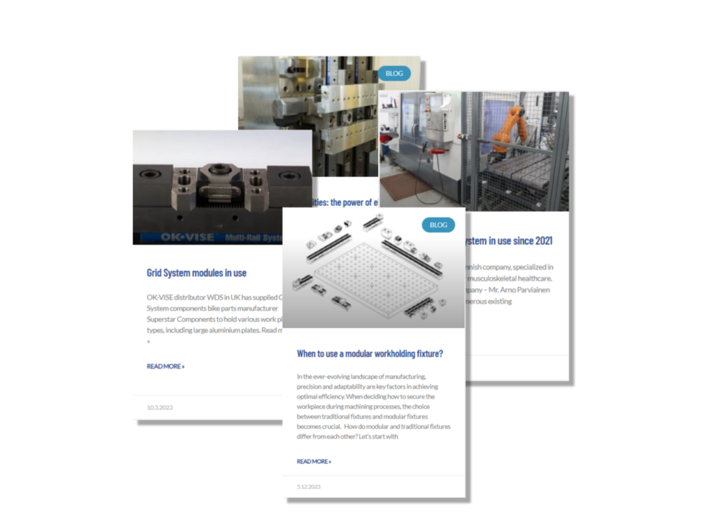
Information Center
The Information Center offers guidance on best practices. Offering fixturing tips on selecting the right fixtures and clamps for different machining tasks.