Fixture design instructions
For all of our systems one of the vital components in fixture design is placing of the modules in their optimal position in the fixture.
Normally the process for clamping one workpiece will be to:
- Place the stopper(s) on the fixture
- Place the workpiece against the stopper
- Place the clamp (with position Aopt) against the workpiece
- Place second stopper(s) against the opposing jaw of the clamp
Instructions for Blank System design
As in every OK-VISE Fixturing Concept system, the basic modules in the Blank System are clamp, stopper, side guide and riser block modules. To resist the clamping and machining forces, a pocket should be machined to the blank plate. Pictures of the pockets are available in the installation instruction.
Basic principle
Following is an example of one possible way to design fixturing. We are assuming here that both the workpiece and the machine tool have been already defined. Once these initial parameters are set proceed as follows:
-Select the fixture plate thickness & material
*nb. Thickness from 28 to 50 mm is the norm
-Both Steel and aluminium plates are used.
*nb. When utilising aluminium always use threaded inserts to ensure reliable installation and clamp operation.
We at OK-vise suggest that it is desirable to consider using an example of fixturing sets at www.ok-vise.com, similar to when using OK-VISE Blank System Fixture sets. We recommend that particular attention is made when considering whether single-directional or dual-directional clamping is needed.
Should you require further technical support in this matter please do not hesitate to request assistance from ok-vise@ok-vise.com .
REFERENCE DESIGN
When you have found a suitable fixturing set (let’s use SK-Z4 as an example) then begin placing the components on fixture plate.
CLAMP POSITIONING
When designing the clamping position, consider clamp module length A=Aopt.
Dimension Aopt is not given for each clamp. If it is not specified, an average of Amin and Amax,can be used.
Aopt = ( Amin + Amax) / 2
where
Amin = clamp module length in rest position
Amax = maximum length of clamp module (with “full stroke”, without any workpiece)
in this example we use KCD-DS2 which is one of our dual directional clamp modules. It has a plate KCD-R1-M, which lifts the clamp up from the fixture plate.
WORKPIECE(S)
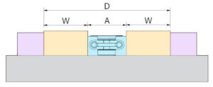
In our reference we are using dual-directional clamping, so we have two workpieces : left and right from the clamp. Please make the dimensioning using average workpiece dimension.
STOPPER(S)
Place the stoppers directly on the workpiece(s)
ENOUGH STROKE ?
-Please ensure that the biggest workpiece also fits into the fixture while loading ( then clamp length A=Amin ).
D > Amax + 2 x W
-Please ensure that there is enough stroke in the clamp so that the smallest workpiece also fits into the fixture while loading ( then clamp length A=Amin )
D < Amin + 2 x W
RISER BLOCKS / PARALLELS
Just like in our example, you may want to lift the workpiece from the fixture plate. Then position some riser blocks under the workpiece(s), here we use KP-1
SIDE GUIDES
Side guides are used to make the positioning of the work piece easier and faster. If machining takes place from only one direction, then a fixed installation of side guides is used. Here we use KG-1.
REPEAT ?
A multitude of fixture sets can be placed on a fixture plate by copying the design.
DESIGN POCKETS
To find correct pocket design for each Blank System module please refer to document BlankInst. We recomend the pocket be made 0.1 mm larger than the modules to ensure ease of installation